Introduction
Electricity has become a basic need for humanity as almost everything we use in our daily life run on it. But if you do not take necessary safety precautions while working with electricity or electrical appliances, it can cause severe injuries or even death. So, before working with AC Mains supply near junction boxes like installing a new device for example, you must turn off the supply and verify that there is no voltage in the switch board. Voltage Testers are devices that detects and indicates presence of voltage in power cables, electrical cords, lighting fixtures, circuit breakers, wires, power outlets etc. A Non Contact Voltage Tester, as the name suggests, is a voltage detector device that doesn’t need any contact with cables, cords or outlets. In this project, I have designed a simple battery powered Non Contact Voltage Tester Circuit that can be used to verify the presence of voltage near all the above mentioned places.
Principle of Operation
Any current carrying conductor produces a small magnetic field around it and the type of magnetic field depends on the type of current passing through the conductor. For example, if AC (alternating current) is flowing through the conductor, then the magnetic field around the conductor also varies periodically. The principle of this circuit is to detect this varying magnetic field and indicate whether voltage is present or not. In order to detect the voltages, I will be using three NPN Transistors. Depending on the amount of base current, the collector – to – emitter current is determined in a transistor. The ratio of collector – emitter current to base current is known as Gain and in case of 2N3904 (which is the transistor used in this project), this value is approximately 200. If the output of one transistor is connected to base of the next transistor, the net gain is the product of individual gains. Similarly, if we add another transistor, the total gain is gain of single transistor raised to the power of 3 (200x200x200).
Circuit Diagram
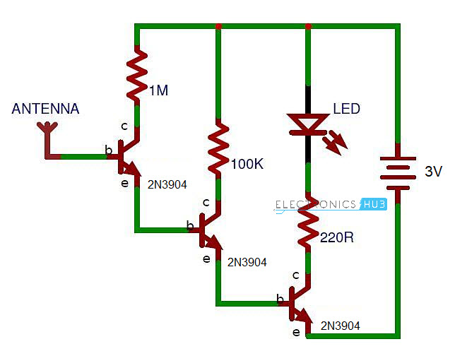
The following is the circuit diagram of Contactless Voltage Tester.
Components Required
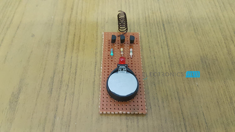
NPN Transistors – 2N3904 X 3 1MΩ Resistor 100KΩ Resistor 220Ω Resistor 5mm LED Small piece of copper wire wound as antenna 3V CR2032 Battery with holder Small perf board
Circuit Design of Non Contact Voltage Tester
A small copper wire (about 12CM) is wound as an antenna and is connected to the base of the first NPN Transistor. If this antenna detects the magnetic field when placed near AC energized objects like cables and switches, it gets induced with a small current (due to electromagnetic induction) and hence activates the first transistor. Since the output of the first transistor drives the second transistor, it gets activated as so on. As the third transistor is activated, the LED is turned ON indicating the presence of a voltage. Additionally, you can place a small buzzer in series with the LED so that it is activated whenever the circuit detects any voltage.
How to Operate Non Contact Voltage Tester?
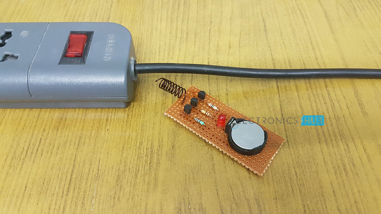
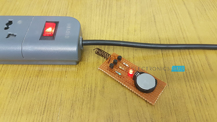
Make the connections as per the circuit diagram on a perf board and solder the components. Connect the battery to the circuit and the device is now powered on. You can place the circuit board in a small box with only the antenna protruding out. Place the antenna near electrical outlets, switches, circuit breakers etc. If voltage is passing though these components and devices, the LED will light up. To save the battery, disconnect it from the circuit when it is not being used.
Applications
This simple Non Contact Voltage Tester can be used in several places and near several objects like cables, cords, outlets, switch boards, junction boxes, circuit breakers etc. to detect voltage without making any contact. Since it is battery operated, you can insert the circuit is a small box and make it portable. It can be used in various fields like security, communication, irrigation, entertainment, environment etc.
Comment * Name * Email * Website
Δ


![]()