Dummy Alarm Circuit Principle:
The main principle of the circuit is to flash an LED for every 5 seconds. The circuit consists of 7555 timer IC as main component. This is a low power IC of 555 series. This 7555 timer is operated in astable mode to continuously and produces the waveform. This output is applied to the high power LED, which flashes for every 5 seconds of delay.
Dummy Alarm Circuit Diagram:
Circuit Components:
555 Timer IC. Resistors R1, R2, R3. Capacitor C1. High power Red LED. Battery. ON/OFF switch
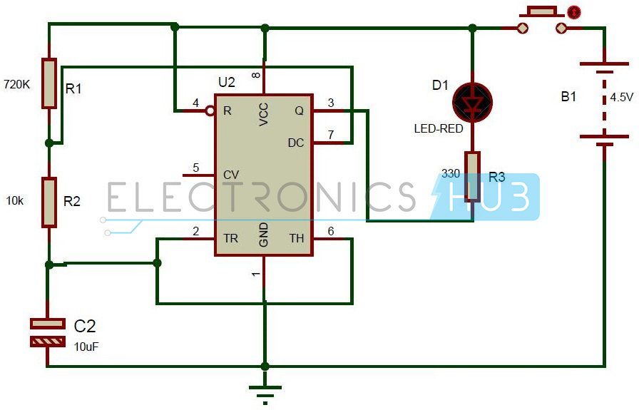
Dummy Alarm Circuit Design:
This circuit consists of 7555 timer IC. It has 8 pins. First pin is connected to ground. Pin2 and Pin6 are shorted and connected to the positive terminal of the capacitor. Negative terminal is connected to the ground. A resistor of 10K is connected to the positive terminal of the capacitor. Another resistor of 680 ohms is connected in series to the 10K resistor. 7th pin is connected between the two series resistors. Other end of the resistor is connected to the battery of 4.5v. 4th pin and 8th pin are shorted and connected to the battery. In the circuit diagram, 8th pin is not shown. The LED with a resistor of 330 ohms is connected to the output pin from the timer i.e. 3rd pin.
Dummy Alarm Circuit Simulation Video:
Dummy Alarm Circuit Working:
Dummy Alarm Project Output Video:
Dummy Alarm Circuit Applications:
As it produces exact delay of 5 sec, it can be used in timing applications. It can be used in cars for security that is, when any theft is detected in the cars it starts flashing for every 5 seconds.
This is dummy alarm and it does not produce any sound, an LED is simply flashed for the given delay. Improper values of R1, R2 and C may cause improper time delays.
Comment * Name * Email * Website
Δ
![]()
![]()
![]()
![]()
![]()

