There are many Audio Amplifier Circuits designed using LM386 IC. The main problem with these circuits is noise and interference. The noise from the Amplifier Circuit designed in this project is considerably less and if designed on a proper circuit board, this will make a great Audio Amplifier. The Audio Amplifier using LM386 is a low power circuit that can deliver a maximum power of 1 Watt (1W) and can be used in a wide range of applications like portable speakers, laptop speakers, etc.
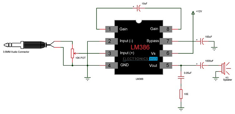
Circuit Diagram of LM386 Audio Amplifier
Components Required
LM386 Audio Amplifier IC 1000 µF Capacitor 100 µF Capacitor 10 µF Capacitor 0.05 µF Capacitor (two 0.1 µF Ceramic Capacitors in series would do the job) 10 KΩ Potentiometer (for input volume control – We did not connect this) 10 Ω Resistor (1/4 Watt) 4 Ω Speaker 12V Power Supply Connecting Wires Breadboard
Introduction to LM386
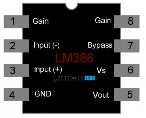
The LM386 is an all – in – one Class AB Audio Amplifier IC that can be used in a variety of applications. LM386 IC has been in use for decades and is still being used as Amplifier in Computer speakers and Portable Stereos. LM386 is a low voltage power amplifier with an inactive power draw of 24mW, which makes it suitable for battery controlled applications. The most common package for LM386 is an 8 – pin DIP. The following image shows the pinout diagram of the IC LM386 . From the pin diagram, it is clear that LM386 is a simple Amplifier IC with possibly minimum external connections. The following table shows the functions of each pin in the LM386 Amplifier IC. Pins 1 and 8 are Gain Control Pins. By default, the Gain of the LM386 Amplifier is set to a factor of 20. When a capacitor is placed between pins 1 and 8, it bypasses the internal resistor (which is responsible for setting the gain to 20) and increases the gain to 200. Pins 2 and 3 are the inverting and non – inverting inputs of the amplifier (internally, they are connected to an OP-AMP). Audio input from devices like microphone, mobile phones, laptops, etc. is given through these pin. NOTE: The inverting input (Pin 2) of LM386 is usually connected to Ground. Pins 6 and 4 are the power supply pins. The maximum power supply to LM386 is 15V. We have used a 12V Power supply in this project. Pin 7 sets the path for decoupling and a capacitor must be connected between Pin 7 and Ground. Pin 5 is the output pin. Proper filtering must be done before connecting the output to a speaker as any DC signal might permanently damage the speaker.
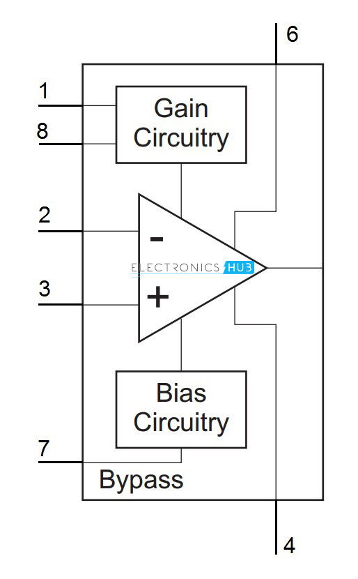
Functional Block Diagram of LM386
Functionally, the LM386 Audio Amplifier IC can be divided in to Amplifier, Gain Control, Bypass, Power and Output. The following image shows the functional block diagram of LM386.
Design of LM386 Audio Amplifier Circuit
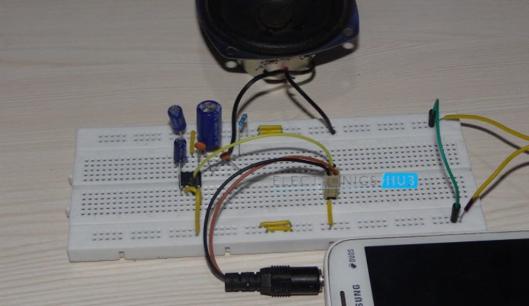
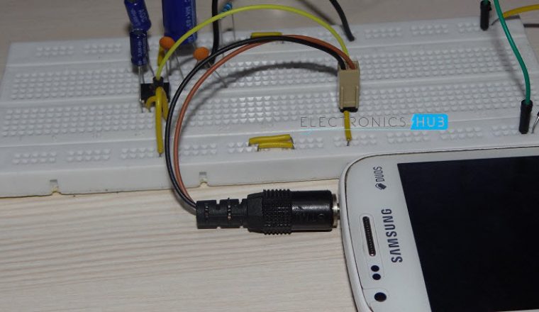
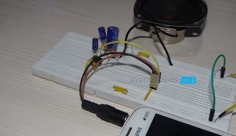
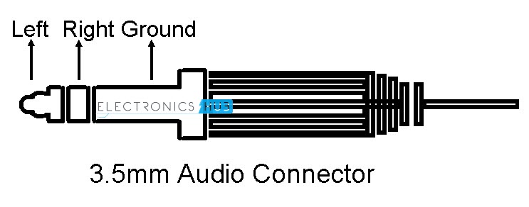
The design of LM386 Audio Amplifier Circuit is very simple. First, connect the power supply pins (Pins 6 and 4) to 12V and Ground respectively. Note that the maximum power supply for LM386 is 15V. Next, we need to connect the input. The input can be given from any audio source like mobile phone or a microphone. We have given the audio input from a mobile phone using the 3.5mm connector. NOTE: Simple 3.5mm connector (without microphone) will have three connections: Left Audio, Right Audio and Ground. Since LM386 is a Mono Audio Amplifier, we need to connect either the Left audio or the Right Audio from the source along with ground. Alternatively, both the channels can be combined to produce a mono channel using appropriate resistors.
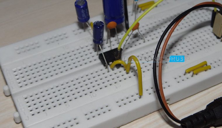
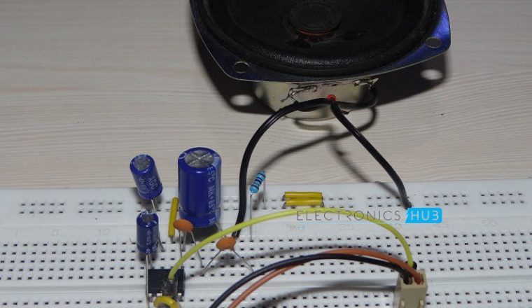
If we want to control the level of the input, we need to connect a 10 KΩ Potentiometer at the input. Since we are doing this project on a breadboard, we did not connect any input volume control POT. Additionally, a small capacitor can be connected in series with the input to filter out the DC Components. Internally, the gain of the LM386 Audio Amplifier is set to 20 (without any gain control circuitry). We connected a 10 µF Capacitor between the gain control pins i.e. pins 1 and 8. Hence, the gain is now set to a factor of 200. Although the data sheet of LM386 says the bypass capacitor at Pin 7 is optional, we found that connecting a 100 µF capacitor was really helpful as it helps in reducing the noise. It can be left open for normal operation. Finally, for the output, first connect a 0.05 µF Capacitor and a 10 Ω Resistor in series between the output pin (Pin 5) and ground. This forms a Zobel Network, a filter consisting of resistor and capacitor in series and is used to fix the input impedance of the driver. Next is the speaker connection. LM386 can drive any speaker within the impedance range of 4 Ω to 32 Ω. We have used a 4 Ω Speaker. Connecting the speaker through a big 1000 µF capacitor was really helpful as it filtered out the unnecessary DC signals.
Working of LM386 Audio Amplifier Circuit
A simple but efficient Audio Amplifier is designed using LM386 Audio Amplifier IC. The working of the circuit is very straight forward as all the work is done by the LM386 IC itself. When the system is powered on and proper audio input is given at the input, the LM386 Amplifier the input signal by a factor of 200 and drives the output speaker. One of the main problems with audio amplifiers like LM386 is the noise. Surprisingly, even though the circuit is built on a breadboard, there was very less noise from the speaker.
Applications
LM386 is already one of the important IC in audio department and is featured commonly portable speakers and laptop speakers. The LM386 Audio Amplifier Circuit can be used for recording voice from microphone, building small speakers that are battery operated, in FM Radio Devices, etc. They can also be used in TV Sound Systems, Line Drivers, Servo Drivers, Ultrasonic Drivers, etc.
lee Comment * Name * Email * Website
Δ
![]()
![]()
![]()

![]()
![]()

