Introduction
USB is an acronym of Universal Serial Bus. The USB standard was developed to simplify the connections between a computer and its peripheral. In fact, almost all the external devices like Keyboard, Mouse, Printer, DVD Writer, Hard Disk Drive, etc. are all being interfaced using the USB port. NOTE: As this project is based on the USB Port, we are referring only to a generic USB port. Now, coming to the project, during low light conditions or power outages, you might not be able to properly see the keys on the keyboard (not a problem if you have a back-lit keyboard). What if you can make a small lamp that is powered using USB and can solve this problem. USB LED Lamp Circuit is a simple solution to this. As the USB port provides 5V at the output, it can be used to light up the simple LED lamp circuit. Another advantage of this Lamp is that you do not disturb other with big lamps as all you need is this small USB Powered LED Lamp.
USB LED Lamp Circuit Diagram
Circuit Components
USB Male Connector Light Emitting Diodes – 5 X 5mm White LEDs Resistors – 100Ω X 5 Perf Board
USB LED Lamp Circuit Design
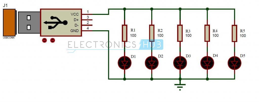
The circuit mainly consists of a male USB Connector. USBs can be mainly divided into two standard types – USB of ‘A’ type and USB of ‘B’ type. These different types of USBs connectors differ in their shapes. Type ‘A’ USB can be used with the upstream devices such as USB hub or host. Type ‘B’ USB can be used with downstream devices such as printers. The cables will have same number of pins but they differ mechanically. Many versions in USB were released. The first version USB 1.0 and 1.1 had the data rate of 12 Mbps.USB 2.0 has data rate of 480 Mbps.USB 3.0 is expected to have data rate of 4.8 Gbps. USB used here is of type ‘A’. It has 4 pins. These pins are VCC, GND, D+, D-. The D+ and D- pins are the data pins. VCC pin outputs the voltage of 5V. The USB LED Lamp with Type ‘A’ male USB connector can be simply connected to the USB port of the computer. LED is a semiconductor device with two leads. Generally LEDs were used for indicating but now-a-days, LEDs are becoming the main sources of lighting in homes, offices, streets, automobiles, etc. An LED is similar to a normal P-N junction diode. The energy emitted is in the form of light when applied with the required voltage, while normal P-N junction diode emits energy in the form of heat.
The color of light emitted depends on the band gap of the semiconductor. The LEDs used here are normal white LEDs. They have voltage drop of 3.6V. The current required by the LEDs is 40mA. Initially these LEDs are limited to the red color, later high power LEDs and other colored LEDs such as blue LEDs, white LEDs etc. were developed. NOTE: Please refer to the data sheet of the LED for the values of forward voltage and current. A resistor of 100Ω is connected between the Light Emitting Diode and the USB. This acts as a current limiting resistor. As the LEDs require maximum current of 40mA to glow with full brightness, they are required to protect from current more than this. So, for that reason, a resistor is to be placed between the LED and the power supply to limit the amount of current flowing through the LED. The supply voltage coming from the USB is 5V and the current drop at the Light Emitting Diode is 40 milli amperes. The following formula can be used to calculate the resistor value. R=V/I where, the value of V is 5 volts and the value of I is 40 mA. So, R= 5V/0.04A =125 ohms But generally, 125 ohm resistor does not exist in real time. Therefore a resistor of 100Ω is used instead of 125Ω. Though it gives an output current of 50 mA, this can be tolerated by the LED.
USB LED Lamp Circuit Simulation Video
How to Design the USB LED Lamp Circuit?
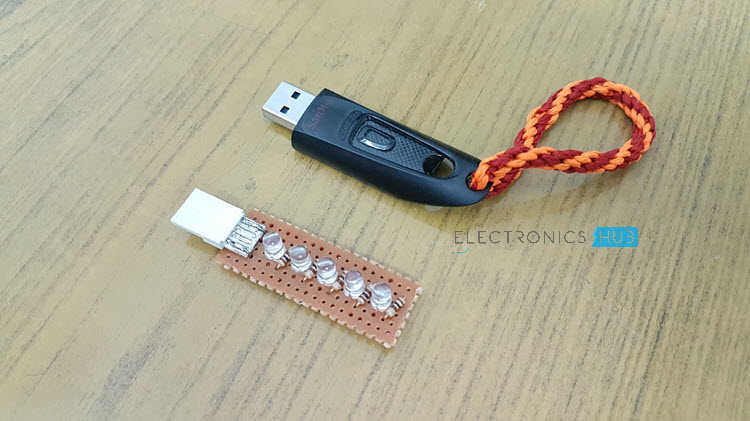
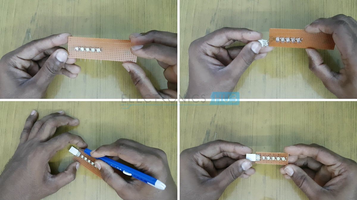
Take a small piece of perf board and solder the Male USB Connector. Then start soldering the LEDs and 100Ω Resistors. Scrape the edges to smoothen the perf board.
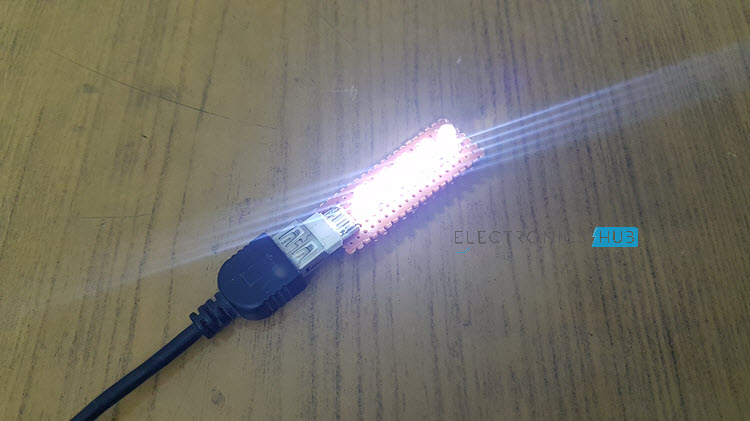
How to Operate USB LED Lamp Circuit?
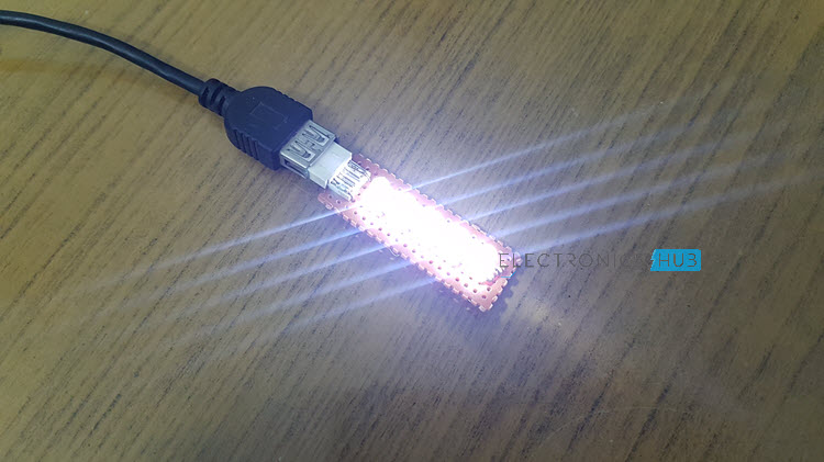
Initially connect the circuit as shown in the circuit diagram. Now insert the USB to the port of the computer. You can observe the lamp glowing Now remove the USB from port. Now lamp is switched off.
USB LED Lights Circuit Advantages
This is simple and inexpensive. This is a portable lamp. No extra source is required.
Applications of USB LED Lamp Circuit
This can be used as an emergency light. Get an idea about Working of Automatic LED Emergency Lights Circuit. This can be used to work with laptop or computer without disturbing the others sleep. This can be used as a reading lamp.
note: Upon connecting the same led to 6v battery it glows constantly. Comment * Name * Email * Website
Δ
![]()
![]()
![]()
![]()
![]()

