There are many wireless communication technologies like Bluetooth, RF Communication, ZigBee, etc. but GSM Technology based communication allows long range, reliable and secure communication. The Wireless Electronic Notice Board using GSM project, as the name suggests, is built around GSM Technology as mobile phones (that communicate through GSM Technology) have become very abundant, cheap and easy to use. NOTE: We need a Mobile Phone to send the Message (Notice) and a GSM MODEM to receive that notice. Related Post: RFID Based Attendance System using Microcontroller
Construction and Output Video
Circuit Principle
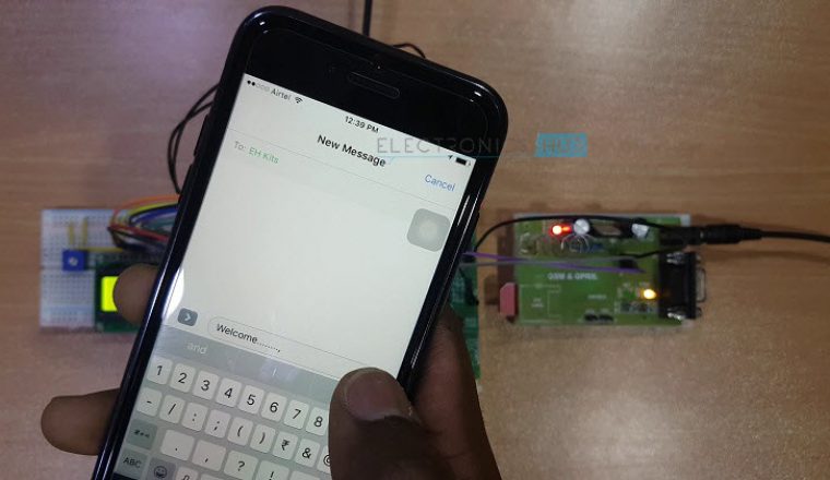
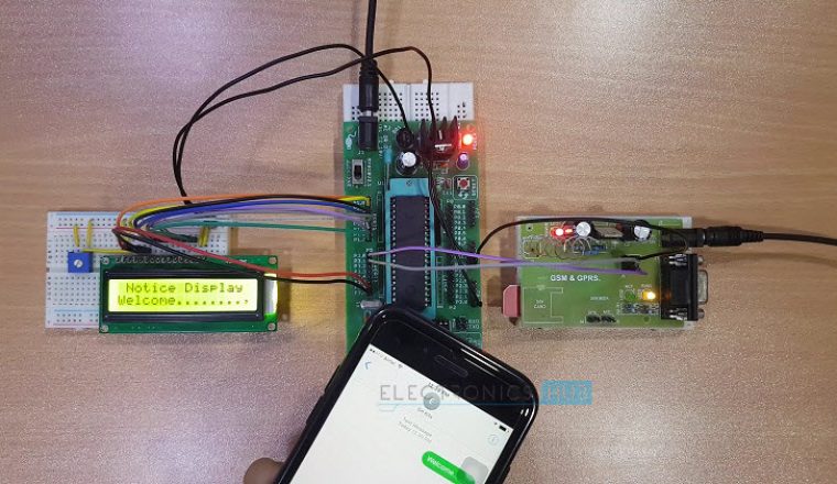
When we send the message from the mobile, the GSM Modem which is connected to the Microcontroller and the display unit, will receive the message. Now, the microcontroller reads the message from the GSM Modem and displays it on LCD. When user sends the message from the mobile, GSM modem sends the below command serially to indicate that a new message is received. +CMTI: “SM”,3 In the above command, number “3” indicates the location of the new message i.e. it is the third message in the inbox. Now you need to read this unread message to display on LCD. The command to read the message from GSM modem is AT+CMGR=3 Here, the number “3” indicates the location of the message to be read. After giving this command to the GSM module, it will send the below command serially. +CMGR: “REC UNREAD”,”MD-WAYSMS”,,”13/05/20,15:31:48+34″ Electronics Hub In the above command, “REC UNREAD” indicates that message is unread message, “MD-WAYSMS” indicates sender mobile number or name, 13/05/20 indicates the date, 15:31 indicates time and Electronics hub is the content of the message. From the above command we need to extract message (Electronics Hub) sent by the user to display it on the notice board (LCD).
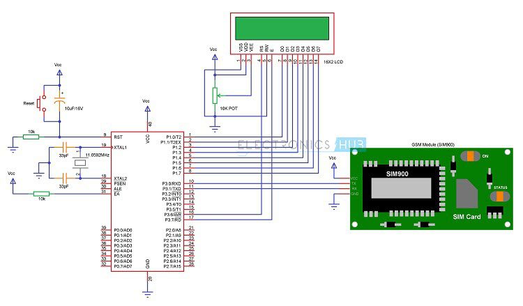
Circuit Diagram of Wireless Electronic Notice Board using GSM
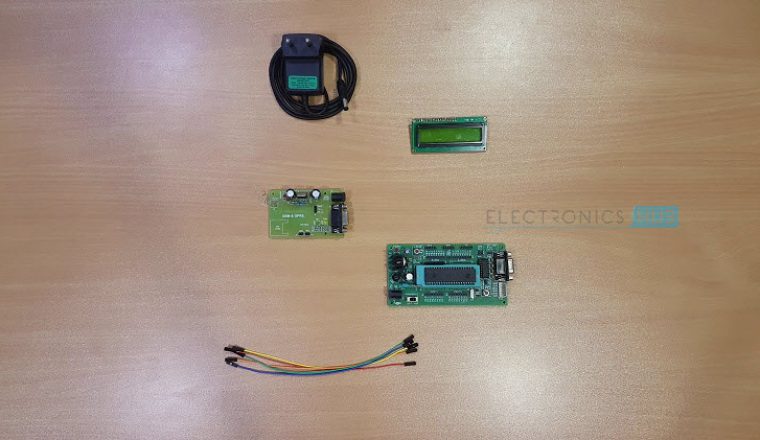
Components for Wireless Electronic Notice Board using GSM
Hardware Requirements
8051 Microcontroller (AT89C51) 8051 Programming board (Programmer with cable) 8051 Development Board SIM 900A GSM MODEM (GSM Module) SIM Card (for inserting in GSM Modem) A mobile phone with a SIM Card already inserted 16 x 2 LCD Display 10 KΩ Potentiometer Connecting wires Power Supply If 8051 Development Board is not available, then you need the following components 2 x 10 KΩ Resistors (1/4 Watt) 2 x 33pF Ceramic Disc type Capacitors Push Button 10µF / 16V Capacitor (Polarized) 0592 MHz Quartz Crystal
Software Requirements
Keil µVision IDE (for writing the program and generating .hex file) Willar Software (for burning the .hex file in to the microcontroller) Proteus (for circuit diagram and simulation)
Circuit Design
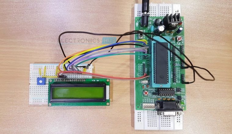
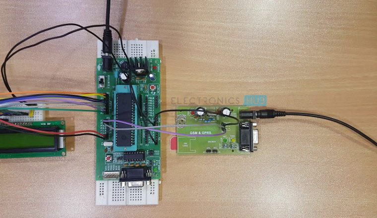
The above circuit of the Wireless Electronic Notice Board using GSM consists of 8051 Microcontroller, GSM Module (Modem) and 16 x 2 LCD. Here, the 16 x 2 LCD is used to display message and is used in 8 – bit mode. Means, we need 8 data lines to display the data. The data lines of the LCD Display are connected to PORT1 Pins. The control pins RS, RW, and E pins are connected to P3.6, GND and P3.7 pins respectively. The GSM Module is directly connected to the microcontroller as the logic levels of both the GSM Modem and Microcontroller are already matched in the GSM Module Board. If there is no level converter on the board, then we need to use MAX232 level converter as a mediator between Controller and GSM to transfer the data. To know more details about max232 refer Max232 Datasheet In order to communicate with the GSM Modem, we need to send some AT commands using serial communication (UART protocol). Here, GSM SIM 900A module is used. This module requires 9600 baud rate. To know more details about GSM go through the article GSM Interfacing with 8051 Microcontroller
Circuit Algorithm
Use below code to display message on LCD wirelessly using GSM while (rx_data() ! = 0x0d); while (rx_data() ! = 0x0a); if (rx_data() == ‘+’) { if (rx_data() == ‘C’) { if (rx_data() == ‘M’) { if (rx_data() == ‘T’) { if(rx_data()==’I’) { while (rx_data() != ‘,’); a = rx_data (); delay_ms (10); tx_string (“at”); tx_data (0x0d); tx_data (0x0a); tx_string (“at + cmgf =1”); tx_data (0x0d); tx_data (0x0a); tx_string (“at + cmgr =”); tx_data (a); tx_data (0x0d); tx_data (0x0a); while (rx_data() ! = 0x0a); while (rx_data() != 0x0a); while (rx_data() ! = 0x0a); for (i=0; i<15; i++) { read [i]= rx_data(); } lcd_stringxy(1,0,read); delay_ms (5000); } } } } }
Circuit Simulation Video
How to Operate Wireless Electronic Notice Board using GSM?
Circuit Advantages
No need of any complex wires to display the message on LCD as it is wireless. Consumes less power and easy to operate. The circuit is portable.
Circuit Applications
Used in bus stations, railway stations, parks, etc. to display the messages wirelessly This Project can also be used in colleges and organizations.
Circuit Limitations
Display unit must have the network to receive the message wirelessly As there is no password any one can send the message to display.
Download Project Code
Are you trying to make the same project or different one? Ans- yes the project is almost same. Give us more details about your project. Ans- in our project we want to transmit the msg recieved by gsm module to lcd display with some other modifications like gsm to mobile acknowledgement, network detection by microcontroller etc. Are you trying to make the same project or different one? Ans- the project is almost same. Give us more details about your project. Ans- it is our final year project. i will be very thankful to you if i get your project code because i am in urgency. please help thankyou so much we want some modifications in it like displaying the previous msg with the current one simultaneously and even want to save the older msg. so can you plz send the code asap some techn ical help is needed plz……. also I want to make a similar kind of project making some modifications… kindly provide me the code… thank you… we want some modifications in it like displaying the previous msg with the current one simultaneously and even want to save the older msg. so can you plz send the code asap Doing the same project as mini project in my college. I have some queries also, whom should I ask ? Please help me. Reply fast. jishnumylapra@gmail.com So ts my humble request to send me project code as there might be use built in function. I will be grateful to you. Thankyou the below given is my email id so please send me. also in uart.h file The function Unsigned rxdata (void) is given. It should be Unsigned char rxdata(void) But when I corrected this it LCD doesn’t show anything +CMTI: “SM”,3 +CMGR: “REC UNREAD”,”MD-WAYSMS”,,”13/05/20,15:31:48+34″ Hi World do you know the reason behind it? Thanks a lot for helping me Doesn’t matter the country that you reside in, if everyone keeps asking for it to be done for them, the future generations of EE’s are going to be in a sorry state of affairs, soon there’ll be nobody that can do it because all they have done is copy and paste most of their lives! Comment * Name * Email * Website
Δ




![]()